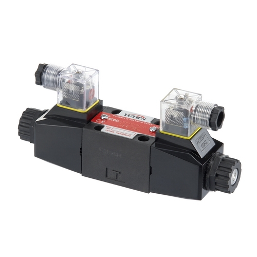
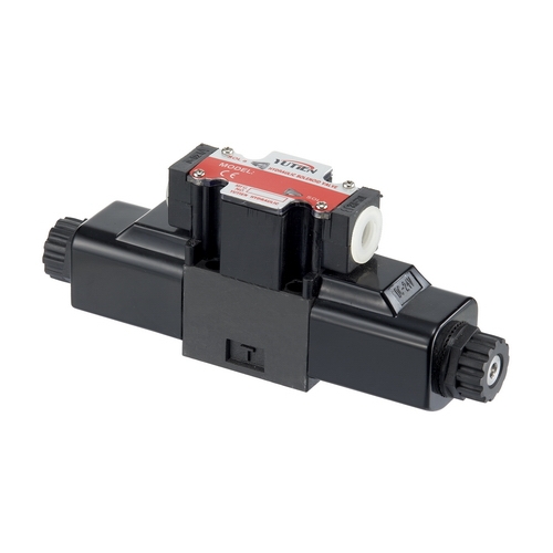
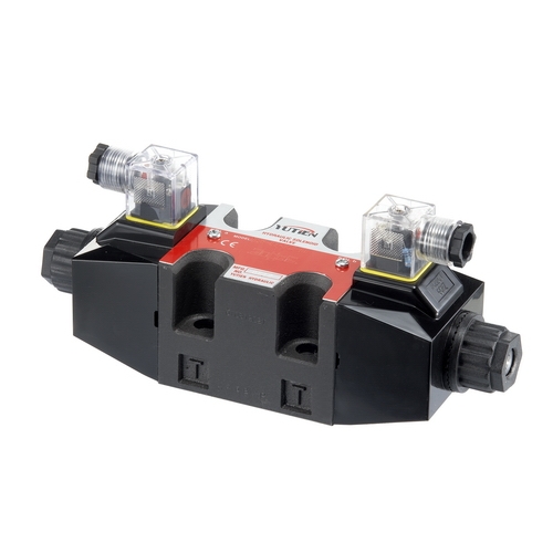
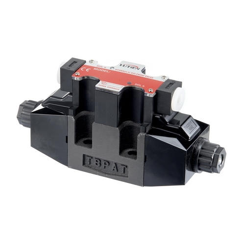
Solenoid Control Directional Valves
Model:DSW
Solenoid Control Directional Valves are electromechanical devices used to control the flow of fluids or gases in hydraulic systems. These valves are commonly used in industrial and mobile applications where precise and reliable control of fluid flow is required.
Solenoid control directional valves are designed to control the direction of flow of the hydraulic fluid, and they are actuated by a solenoid coil. When an electrical current is applied to the solenoid coil, it produces a magnetic field that moves a plunger, allowing the hydraulic fluid to flow in a particular direction.
These valves are available in a range of sizes and configurations, including 2-way, 3-way, and 4-way valves. They can be designed for direct mounting on actuators or can be remote-mounted using a manifold system. Some solenoid control directional valves are designed for high-pressure applications, while others are optimized for low-pressure systems.
Download
Add to inquiry
Solenoid control directional valves are designed to control the direction of flow of the hydraulic fluid, and they are actuated by a solenoid coil. When an electrical current is applied to the solenoid coil, it produces a magnetic field that moves a plunger, allowing the hydraulic fluid to flow in a particular direction.
These valves are available in a range of sizes and configurations, including 2-way, 3-way, and 4-way valves. They can be designed for direct mounting on actuators or can be remote-mounted using a manifold system. Some solenoid control directional valves are designed for high-pressure applications, while others are optimized for low-pressure systems.
Feature
• The main body has double grooves for oil return to increase the passing flow and the operating pressure.
• New CNC precision machining, accurate size. With non-right-angle spool designed to reduce the cutting edge or sliding block issues caused by high pressure.
• Internal resistance is greatly increased.
• Internal back pressure is greatly increased.
• Oil-immersed type solenoid design with stable action and low noise.
• One-piece coil, with good water-proof effect, good heat dissipation and high temperature resistance.
• 3-positions/4-ways or 2-positions/4-ways spool type directional control valve operated by 5-hole solenoid. Suitable for block or base plate installation.
• Solenoid valve installation dimensions are in line with international standards.
• With neon light to indicate the direction of action.
• DIN Type plug-in and Terminal Box type connection, with direction indicator light on both sides.
Model Description
| DSW |
-02 |
-3C60 | R | -D |
-A110 |
| Model/Series |
Thread Code (Inch) |
SpoolActuated /Function |
Assembly Type |
Connection Type |
Coil Type |
| Solenoid Operated Directional Control Valves |
02 : 1/4" 03 : 3/8" |
Please refer to the spool function table (p. A4~A5) |
None: standard R: Reverse |
B: Terminal Box Type D: Plug-In Type (DIN) |
AC:A110 AC:A220 DC:DC12 DC:DC24 RF:R110 RF:R220 |
Specification
| Model/Type |
Rated Flow (Max.) L/min |
Operating Pressure (Max.) Kgf/c㎡ |
Back Pressure (Max.) Kgf/c㎡ |
Conversion Ferquency Times/min |
|
DSW-02 |
60 | 215 | 70~160 | 240 |
|
DSW-03 |
100 |
DSW-02
| Voltage/ Current Type | AC | DC | RF | |||||
| Operating Voltage (V) | 110 | 220 | 12 | 24 | 110 | 220 | ||
| AC Frequency (Hz) | 50 | 60 | 50 | 60 | ||||
| Holding Current (A) | 0.43 | 0.43 | 0.22 | 0.22 | 1.72 | 1.05 | 0.38 | 0.19 |
| Inrush Current (A) | 1.45 | 1.45 | 0.89 | 1.01 | ||||
| IP Ratings | IP65 | |||||||
| Coil/Wire Level | PEWH | |||||||
| Coil Temperature Resistance | 180℃ | |||||||
DSW-03
| Voltage/ Current Type | AC | DC | RF | |||||
| Voltage/ Current Type | 110 | 220 | 12 | 24 | 110 | 220 | ||
| Operating Voltage (V) | 50 | 60 | 50 | 60 | ||||
| AC Frequency (Hz) | 0.62 | 0.69 | 0.27 | 0.33 | 2.03 | 1.48 | 0.54 | 0.27 |
| Holding Current (A) | 3.41 | 4.14 | 1.58 | 1.95 | ||||
| Inrush Current (A) | IP65 | |||||||
| IP Ratings | PEWH | |||||||
| Coil/Wire Level | 180℃ | |||||||
| Coil Temperature Resistance | ||||||||
 Download